Dumping AVR Fuse Settings In Bash November 5, 2009 No Comments
I’m starting to get more into AVR programming, and reading / writing fuses is a pretty essential skill. The fuses can be easily read with avrdude, and the Engbedded Fuse Calculator does a wonderful job of interpreting the fuse bytes for you. But I got tired of typing out the avrdude command, then opening up firefox, going to the Engbedded site and copying and pasting the fuse bytes into the input fields every time I wanted to check fuse settings (granted, not that often, but still…).
So, naturally, I wrote a bash script: avr-fusedump. Just give it the name of your programmer and the AVR chip that you have connected, and it will run avrdude, print out the high, low, and extended fuse bytes, and open up the Engbedded Fuse Calculator site with the current fuse settings of your AVR chip. Example:
$ avr-fusedump -c usbtiny -p ATmega328P
lfuse	0xFF
hfuse	0xD9
efuse	0x07
And the following page was opened:
The avr-fusedump script can be downloaded here.
Cenzic POV Fan Toolkit October 8, 2009 No Comments
In order to make hacking my Cenzic POV fan easier, I created a small tool kit consisting of a couple of Python scripts to aid in the creation of character maps and EEPROM images for the fan.
The first Python script, ascii2cenzic.py, was mentioned in my original article; you simply pass it the ASCII text that you want the fan to display, and it will generate the binary data that you need to load onto the fan’s EERPOM using PonyProg. It has been updated to support uppercase alpha numeric characters, some punctuation, and smiley and frowney faces.
If you want to display an image that the ascii2cenzic script doesn’t support, you have to figure out the necessary byte patterns. This can be time consuming, so the second script included in the tool kit is graph2hex.py. Graph2hex will take a 5×7 character ASCII art image and generate the five byte sequence needed in order to display that image on the fan. There are two important notes regarding the use of this tool:
- The image MUST be 5×7 characters, no more, no less
- Zeros in the ASCII art image will be where the LEDs are turned on; anything else is considered “off”.
Hacking The Cenzic POV Fan October 6, 2009 20 Comments
At Black Hat this year the Cenzic booth was giving away some portable personal fans, with a slight twist: these were persistence of vision fans. I’d only ever seen one other POV fan, and it wasn’t portable, so the Cenzic fan seemed like a prime candidate for hacking.
Not having any prior experience with POV, I started poking at things to see how it worked. It turns out that Cenzic made it very easy to access the fan’s EEPROM chip, and with a simple RS232-to-I2C interface you can re-write the EEPROM on this device to make it display whatever you like:
Building A Boxee Remote Control September 28, 2009 6 Comments
After configuring my Boxee server to distribute video through the coax cabling in my house, I needed a way to control the Boxee server from other rooms.
I built a remote control system that uses an ATMega328 microcontroller and a Linksys WRT54G to read IR codes from standard TV remote controls and relay them over the WiFi network to a Python script running on the Boxee server.
Here’s how it works:
- An IR receiver is attached to an ATMega328 microcontroller (Arduino), which reads the IR codes from standard TV remote(s).
- The microcontroller is also connected to the serial port of a WRT54GSv4, which is connected as a client to my WiFi network.
- When the microcontroller receives an IR code, it pipes the code through netcat to a Python script running on the Boxee server.
- The Python script finds the keyboard key in its lookup table that corresponds to the received IR code and then simulates that key press using the xte utility.
Installing OpenWRT On The GT-704WG September 17, 2009 11 Comments
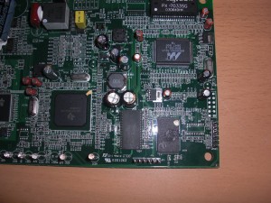
I recently picked up an ActionTec GT-704WG DSL router from the thrift store ($15) and wanted to flash it with OpenWRT. Checking out Google and the OpenWRT Wiki, some work has been done on the GT-701WG, but specific information for flashing the GT-704 was scarce. The GT-704 hardware is based on the AR7 from Texas Instruments, and is nearly identical in specifications to the GT-701:
Platform: Texas Instruments AR7, 150MHz
Flash: 4MB
RAM: 16MB
Ethernet: 4 Ports
Wireless: TI ACX111, 802.11b/g
The firmware install is pretty straightforward, once you get the commands right. The process is very similar to that documented for generic AR7 devices, but not exactly the same. It helps to have a terminal connected to the JP603 serial port (ttys0, 38400, 8N1)during this process as well, but it is not necessary:
The pinout for the serial port is, as pictured, from bottom to top: ground, transmit, receive, unknown, Vcc, unknown.
Flashing Asus WL-520GU Firmware Via TFTP September 11, 2009 No Comments
Today a friend and I were struggling to re-flash an Asus WL-520GU with OpenWRT via TFTP. The router had been previously flashed with DD-WRT, and of course the Web-based firmware update did not recognize the OpenWRT trx file as a valid image (there is currently no OpenWRT .bin file available for the WL-520GU); this left TFTP as the next best option for flashing the firmware.
Usually, it is helpful to have a serial console connected to the router while doing a TFTP transfer, so that you can see when the bootloader (CFE, in the case of the Asus) is listening for TFTP connections, as with the Linksys WRT54G:
CFE version 1.0.37 for BCM947XX (32bit,SP,LE)
Build Date: Thu Mar 24 16:31:45 CST 2005 ([email protected])
Copyright (C) 2000,2001,2002,2003 Broadcom Corporation.Initializing Arena
Initializing Devices.
et0: Broadcom BCM47xx 10/100 Mbps Ethernet Controller 3.90.39.0
CPU type 0×29008: 200MHz
Total memory: 8192 KBytesTotal memory used by CFE: 0×80300000 – 0×80399700 (628480)
Initialized Data: 0x8032F870 – 0x80331F50 (9952)
BSS Area: 0x80331F50 – 0×80333700 (6064)
Local Heap: 0×80333700 – 0×80397700 (409600)
Stack Area: 0×80397700 – 0×80399700 (8192)
Text (code) segment: 0×80300000 – 0x8032F870 (194672)
Boot area (physical): 0x0039A000 – 0x003DA000
Relocation Factor: I:00000000 – D:00000000Committing NVRAM…done
Device eth0: hwaddr 00-40-77-BB-55-10, ipaddr 192.168.1.1, mask 255.255.255.0
gateway not set, nameserver not set
Reading ::
Unlike the WRT54G however, the WL-520GU bootloader did not specify its IP address, and the usual 192.168.1.1 did not work; watching the network traffic while attempting the TFTP transfer revealed that this address was not responding to ARP requests at all. Additionally, while the WRT54G waits for a TFTP connection for a few seconds before timing out, the WL-520GU only listens for about one second before timing out and loading the kernel. Such a short time period, coupled with not knowing the bootloader’s IP address, made flashing via TFTP nearly impossible.
The solutions to both these problems were found (directly and indirectly) through DD-WRT’s WL-520GU Wiki page. By holding down the reset button on the router on boot up, the bootloader will enter hardware restoration mode and perpetually listen for TFTP connections rather than continuing with the boot process. This can be confirmed by watching the serial console output; you should see repeating messages that read: “Reading :: Failed.: Timeout occured”. The power LED should also be blinking slowly when the router is in hardware restoration mode.
Once you have the router constantly listening for TFTP connections, you still need to know the IP. This was discovered by downloading the Asus restoration utility and monitoring the network traffic it generated. This revealed that the router’s bootloader IP address was 192.168.1.49. With the router in hardware restoration mode and knowledge of the bootloader IP address, it was easy to upload the firmware via TFTP:
tftp> mode binary
tftp> trace
tftp> connect 192.168.1.49
tftp> put openwrt-brcm-2.4-squashfs.trx
sent DATA <block=1, 512 bytes>
received ACK <block=1>
sent DATA <block=2, 512 bytes>
received ACK <block=2>
…
Very Simple Vibration Sensor June 12, 2009 3 Comments
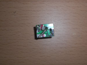
Sometimes when working on a project you may find that you need a vibration sensor. These are useful for detecting footsteps, tremors, wind, etc. Accelorometers can be used, but are a costly solution if you simply want to detect vibrations and are not concerned with gathering precise measurements. Out of curiosity one day, I cut open an Urchin ball to examine the circuitry they use for detecting vibrations / shock. I found that they use a light spring as a very simple, but effective, shock sensor:
The above circuit is enclosed in a small hard plastic ball, placed inside the Urchin ball, which prevents the spring from being physically struck as the ball is thrown around. When the spring vibrates, it strikes the pad on the circuit board, completing a connection and initiating the flashing light sequence. By adjusting the height of the spring above the pad, the vibration detector can be made quite sensitive; even a slight tap on the table or a gentle breeze will set it off:
Just goes to show that you shouldn’t over think your problem: the simplest solution is usually best. I’m thinking that I’ll have to use this for something this holloween…
Diamagnetic Levitation June 10, 2009 No Comments
Ever tried to levitate a magnet with another magnet? The trick is to place a diamagnetic material in between the two magnets. Normal magnets have poles, where opposite poles attract and like poles repel; diamagnetic materials repel both magnetic poles equally, and can be used to balance out the force of attraction between two magnets. Getting a magnet to hover in the air can be a bit touchy, but it can be done without too much trouble.
Bismuth and pyrolytic graphite are both diamagnetic and can be obtained relatively cheaply. You’ll also want a small neodymium magnet to levitate, and any normal ceramic magnet can be used to do the levitating. I purchased a couple strips of pyrolytic graphite and a 2mm neodymium cube magnet from SciToys and used a small ceramic magnet that I’d bought from Radio Shack. The idea is to place the pyrolytic graphite between the neodymium magnet and the ceramic magnet, with the ceramic magnet above the graphite, and the neodymium magnet below. Then slowly adjust the height of the ceramic magnet until you get the neodymium magnet to hover between the ground and the graphite. The graphite should be placed close to the neodymium magnet, and you can put a second piece of pyrolytic graphite below the neodymium magnet for additional stability, but with careful adjustment only one piece is necessary.
So, here is my “levitation device” built primarily from leftover metal covers that come with Radio Shack’s plastic project enclosures (note that all non-magnetic metal was used of course). No electricity or optical illusions, just the wonders of magnetism:
How Crystal Radios Really Work June 8, 2009 5 Comments
Almost anyone who has tinkered with electronics has built a crystal radio. I’ve always marveled not only at how amazing these little devices were, but also at the lack of descriptions regarding their inner workings. Descriptions of crystal radios almost invariably use some terminology synonymous with, “The detector changes the back and forth radio wave electricity into one way sound electricity…“; well, that’s nice, but how does it do that? Why does it work? What do we mean by “radio wave electricity” and “sound electricity”?
Before examining a crystal radio circuit, it is important to understand where crystal radios get their power from. One of the things that makes crystal radios so interesting is that they require no power source. Well, that’s not entirely true, as there has to be some energy coming from somewhere in order to make your speaker / headphones vibrate. Crystal radios get this energy from the radio waves themselves; in fact all radios use this same energy, although modern radios require additional power sources to amplify the relatively weak energy supplied by radio waves.
Radio waves are in many ways similar to the 60Hz AC power that you have in your house; both are forms of electrical energy, and both have currents that alternate direction. The electrons that are responsible for generating radio waves however, alternate direction much faster than the electricity in your power lines, typically switching direction millions of times per second. When we talk about electricity, we usually are referring to the electromagnetic fields that transfer power from one place (your electric company) to another (your computer, lights, phone charger, etc). That is exactly what radio waves are: electromagnetic fields. So, think of radio transmitters as small electric companies that send you very small amounts of electric energy, except in stead of sending it through wires, they send it through the air. Einstein’s description of radio is perhaps the most eloquent:
You see, wire telegraph is a kind of a very, very long cat. You pull his tail in New York and his head is meowing in Los Angeles. Do you understand this? And radio operates exactly the same way: you send signals here, they receive them there. The only difference is that there is no cat.
Baby Monitor RF Repeater June 1, 2009 No Comments
After I restored my Crosley 516, I was faced with a new problem: what was I going to use it for? Short wave reception was non-existent with a short wire antenna, and there’s nothing that I particularly care to listen to on AM; what I really wanted to do was listen to some old time radio! I’d seen other projects that replaced the guts with Internet radios, but since the electronics worked just fine I really wanted a way to stream audio from my computer to the radio without any modifications to the original radio circuitry itself.
The obvious solution was to build a small AM transmitter and modulate the signal with the audio output from my computer. I built a very simple, low-cost, low-power AM transmitter:
However, I had some self-imposed restrictions to overcome:
- The receiver could not pick up the low-power transmitter unless the two were right next to each other.
- A larger antenna would improve reception, but I didn’t want to have a large piece of wire hanging off the back of the radio since I planned on placing it in the living room.
- Adding an amplifier to the transmitter would improve reception, but would make the circuit more complex; more importantly, I would have to be careful about the FCC’s part 15 rules.
- I didn’t want to put a computer in the living room – most of the ones that I have laying around are noisy, so it would be best to keep the audio source (computer) in the basement.


